Displacement Maps, Normal Maps, and Textures in React Three Fiber
Creating realistic landscape or terrain geometry is required almost any time you are working on an outdoor 3D scene. There are lots of ways to approach this. You can generate terrain procedurally using noise functions, you can hand model it in the mesh, or you can take real world terrain data and convert it into textures that deform an otherwise flat piece of geometry.
We are going to learn how to create a landscape using a type of real world scientific elevation data called Digital Elevation Models or DEMs for short. Once we have acquired this raw elevation data, we can convert it in to a set of textures which can be applied to a Three.js material allowing us to deform geometry via a displacement map and a normal map.
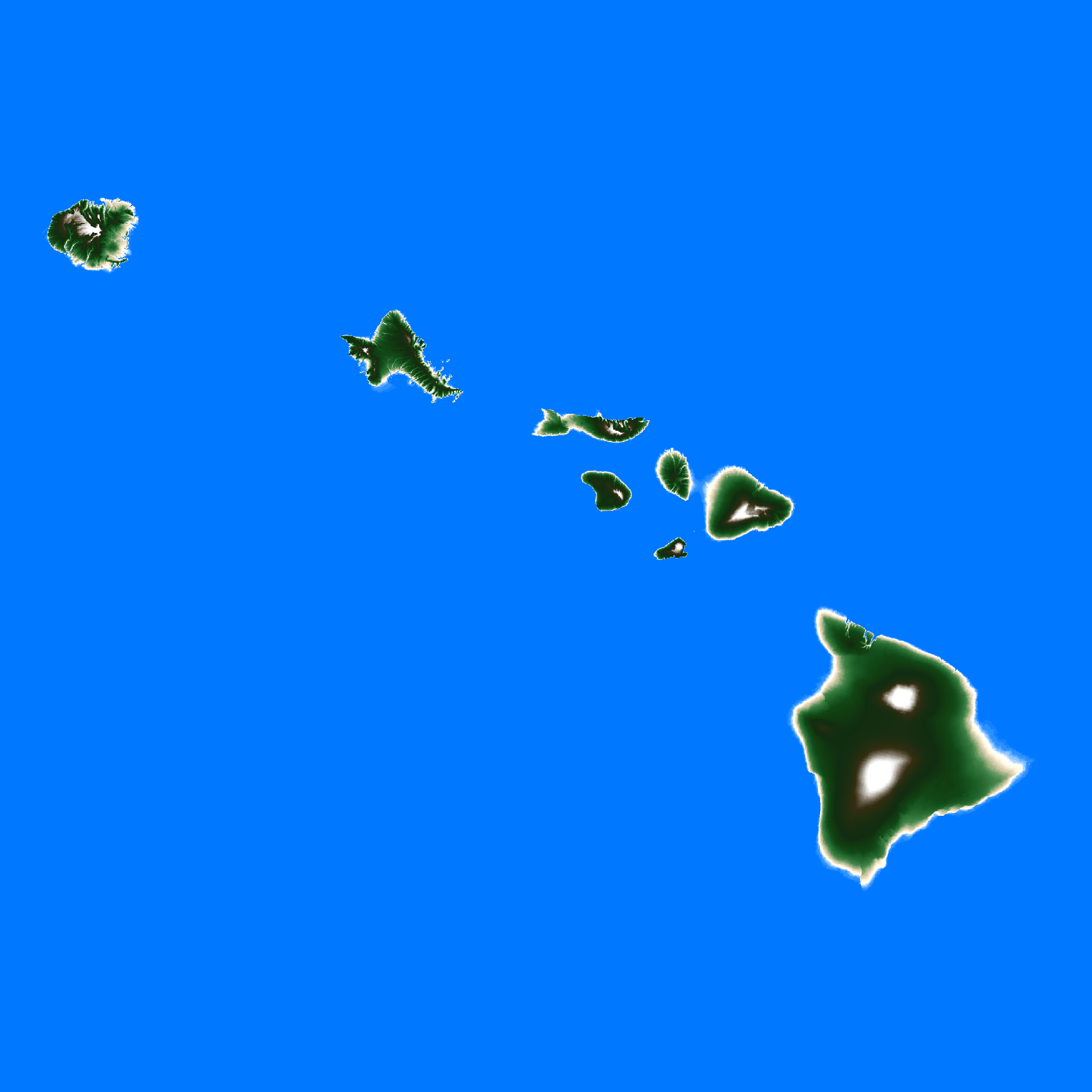
In this tutorial we will build the following scene of the Hawaiian Islands using just a single piece of planeBufferGeometry, and 3 textures. One texture for the height of the terrain to be used as a displacement map, another texture for the "normals" which tell the 3D renderer the direction each vertex is facing after being transformed by the displacement map so that shadows can be applied correctly, and one for the color. We will learn how to create these three textures, and then how to apply them to the scene.
Where to Get Real Elevation Data to Create a Height Map
The first texture we need is a height map to drive the displacement of vertices. This texture will determine how high or low each point on the geometry is once it is applied, and it should be a black and white image. Completely white pixels will represent the highest points, and completely black will represent the lowest points.
One good place to get this data is from the GIS or Geographic information systems field. There are many scientific and research organizations which provide access to elevation and mapping data.
There is a specific type of file commonly used in the GIS community called a DEM (Digital Elevation Model) which is a close match to our needs because it represents elevation as black and white pixels on a map. If you search for (your location here) DEM there is a decent chance you will find a result. For this example we can use DEM files of the Hawaiian Islands. These files are provided by the University of Hawaii School of Ocean Science and Technology.
Open the DEM Files in QGIS to Capture Them as a Black and White Height Map Texture
Sometimes you can find these maps as images and you can just save them and use them as textures. More commonly however they are created using special file formats used in the GIS profession for mapping software. To open these types of files and convert them to an image you will need to use the same GIS mapping software they use, in this case the awesome and free QGIS. You can follow the steps below to open almost any DEM file and capture it as a black and white image ready for us to use as a displacement map texture.
Note: A good displacement map texture should be sized as a square with each side being a power of two. So 1024 2048 5096 etc. The tallest points on the texture should be pure white, and the lowest should be pure black, with shades of gray representing the steps in between. Also keep in mind, the higher quality your black and white image is the better the resulting terrain will look.
- Download QGIS
- Extract the zip file if you downloaded a DEM file contained in a zip.
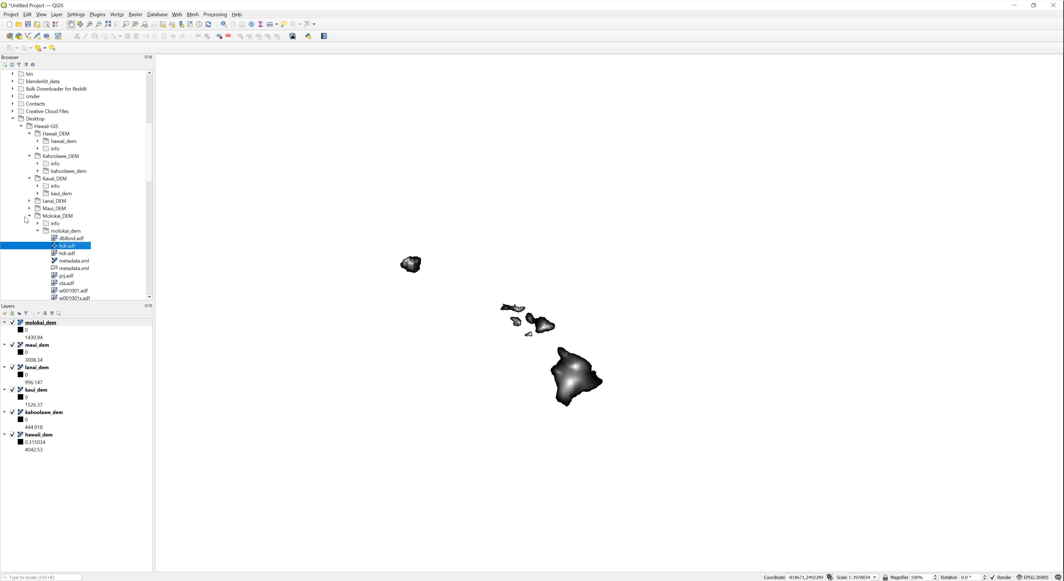
- Open All of the DEM files using QGIS. The software can open more than one DEM file at a time and will automatically apply them as separate layers in the viewport. This allows you to combine multiple files in one image. The map of the Hawaiian islands used in this tutorial was created from different DEM files for each Island in the chain.
- After opening all of the DEM files you want to use, just screenshot them and save the screenshot as a simple image format like PNG or JPG.
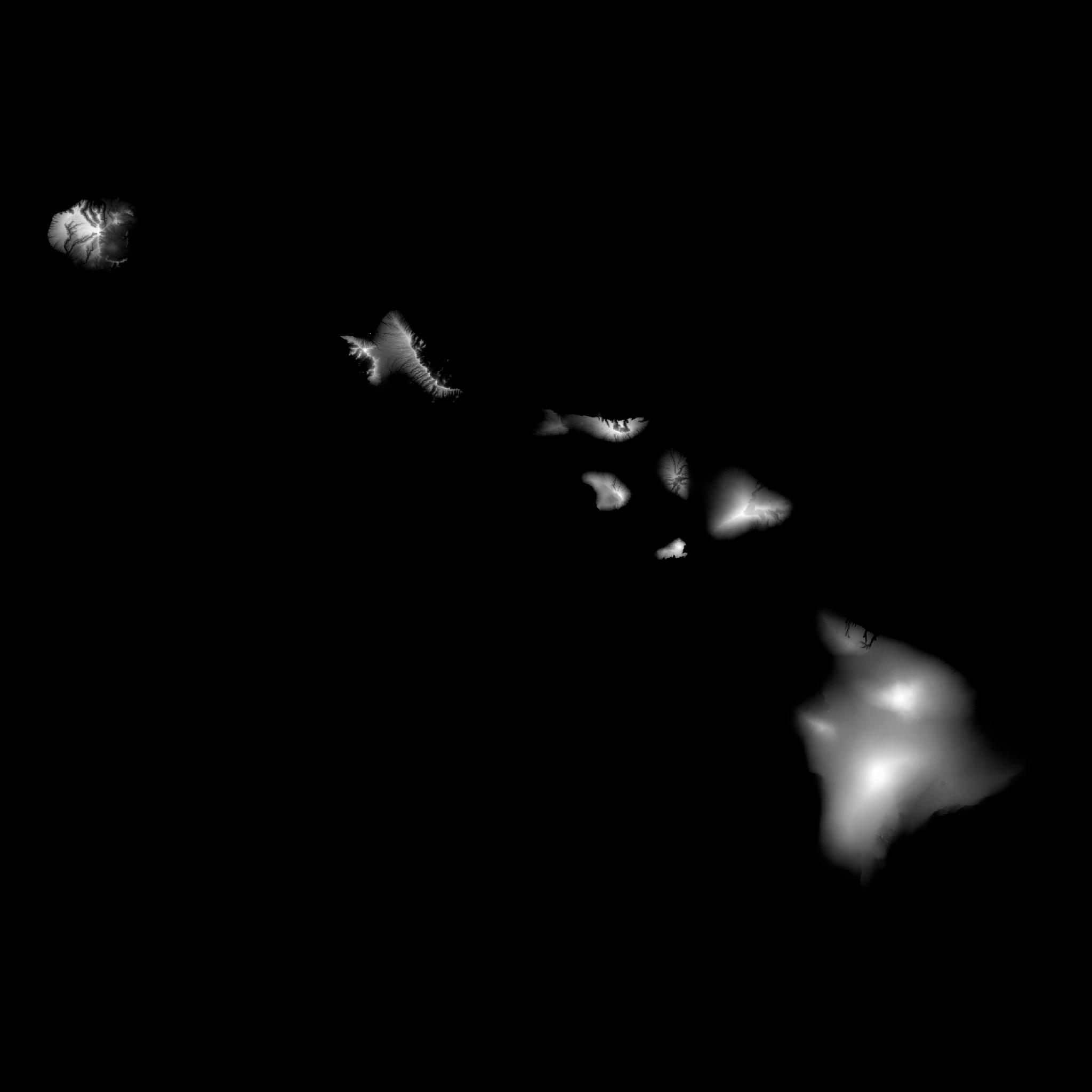
- Post process the image in any image editor to make it suitable for use as a height map texture. This step includes resizing, cropping, and making any other modifications you deem necessary.
The end result should look like this. If you don't want to make your own texture you can just use this one.
Generate a Normal Map from the Height Map
You will also need a normal map. A normal map allows the 3D renderer to create shading and works similarly to a bump map. The R,G, and B values of each pixel in a normal map represent the X,Y, and Z rotation of the vertices in a mesh and can be used to calculate lighting on otherwise flat surfaces. You can create a normal map directly from your height map using this tool. Open your black and white height map and it should automatically convert it to a normal map for you. Save the resulting file back to the same directory as your height map and call it something like normals.png
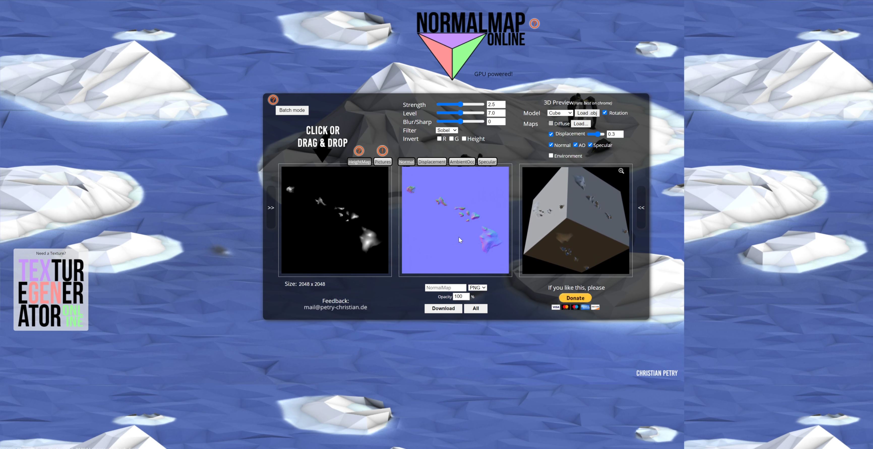
If everything went correctly you should have a new file that looks like this.

Generate a Color Map from the Height Map
Now we have some textures to drive the shape of the geometry. But it would be nice if we also had a color texture to apply.
The cool thing about landscapes is that the color is roughly a function of the elevation. Sea Level is blue ocean, just above that might be golden beaches, then green forest, then grey rocky mountains, then white snow covered peaks.. etc.. This is not a perfect system, but it's good enough to get a surprisingly far way with very little manual work. Be creative here, you can tweak your color map to get some really cool effects.
You can create a color texture directly from the height map by using the Gradient Map tool found in many image editors. If you have any trouble with this feel free to just use the colors texture provided below.
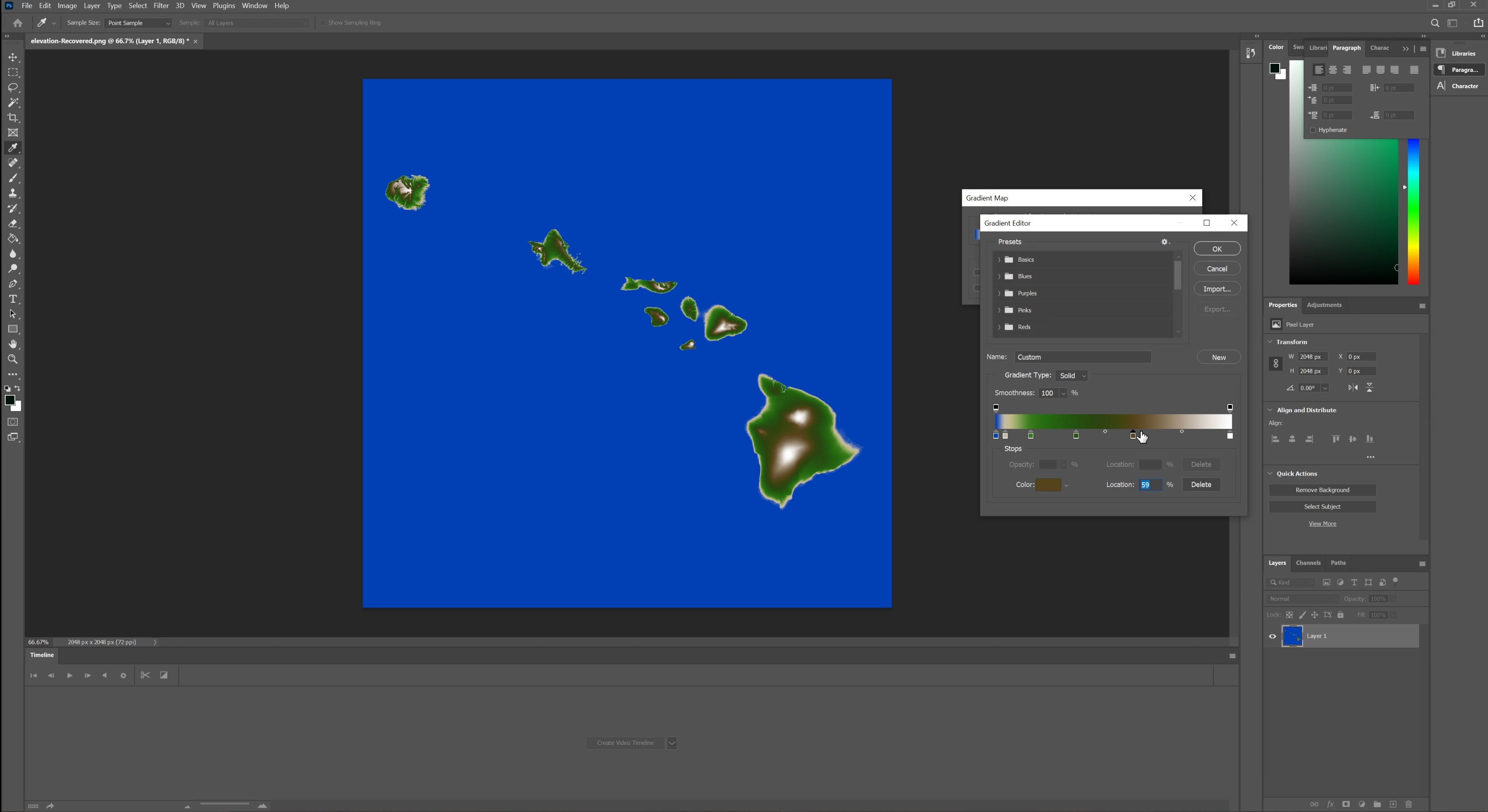
Once you have applied a gradient to the height map, you should get a new image that looks like this.
 Download Full Size Color Texture
Start a New React Three Fiber Project
You can start a new React Three Fiber scene by cloning this Code Sandbox Template. React Three Fiber Template
Once you have the scene cloned you should see a spinning cube. Replace the entire App.js file contents with the following code to get started.
import React, { Suspense } from "react";
import { Canvas } from "react-three-fiber";
import * as THREE from "three";

import { Plane } from "drei";
import "./styles.css";

const Terrain = () => {
  return (
    <group>
      <Plane
        rotation={[-Math.PI / 2, 0, 0]}
        position={[0, -3, 0]}
        args={[64, 64, 1024, 1024]}
      >
        <meshStandardMaterial attach="material" color="white" metalness={0.2} />
      </Plane>
    </group>
  );
};

export default function App() {
  return (
    <Canvas>
      <pointLight intensity={2} position={[7, 5, 1]} />
      <Suspense fallback={null}>
        <Terrain />
      </Suspense>
    </Canvas>
  );
}
This will create a desolate scene with a single plane sitting slightly below the camera, and a light. It should look like this.

Apply the Three Textures to the Plane
First you will need to upload all 3 of the textures you created (or saved) in the previous step to the static directory in the Code Sandbox. Refer to the completed exercise if you need help finding where they should go. Also if you used different file names you may need to adjust the code below to match.
Add the Displacement Map
We can start with the displacement map. We add a displacement map by loading the black and white elevation texture with a useLoader hook, and then attaching it to a displacementMap prop on the material. Don't forget to import useLoader from react-three-fiber.
Also notice how the Plane component has an args prop which is getting an array with four integers in it. These are the args for the planeBufferGeometry type in Three.js. The first two are the length and width size. The third and fourth however are the number of subdivisions in the plane. The number of subdivisions determines how many vertexes the plane mesh has. This is very important when applying a displacementMap because a displacement Map will move the vertices up and down according to how light or dark each pixel is. Effectively the number of subdivisions is the maximum resolution of your deformation. If you make the numbers too low, the plane can only deform in large chunks. Try changing the two 1024 numbers to something like 16 and watch what happens.
import React, { Suspense } from "react";
import { Canvas, useLoader } from "react-three-fiber"; // highlight-line
import * as THREE from "three";

import { Plane } from "drei";
import "./styles.css";

const Terrain = () => {
  const height = useLoader(THREE.TextureLoader, "elevation.png"); // highlight-line
  return (
    <group>
      <Plane
        rotation={[-Math.PI / 2, 0, 0]}
        position={[0, -3, 0]}
        args={[64, 64, 1024, 1024]}
      >
        <meshStandardMaterial
          attach="material"
          color="white"
          metalness={0.2}
          displacementMap={height} // highlight-line
        />
      </Plane>
    </group>
  );
};

export default function App() {
  return (
    <Canvas>
      <pointLight intensity={2} position={[7, 5, 1]} />
      <Suspense fallback={null}>
        <Terrain />
      </Suspense>
    </Canvas>
  );
}
After doing this you won't notice a huge difference, but you should see a subtle bulge in the plane where the geometry has been transformed. You won't see the lighting and shadows behave properly until after the next step.

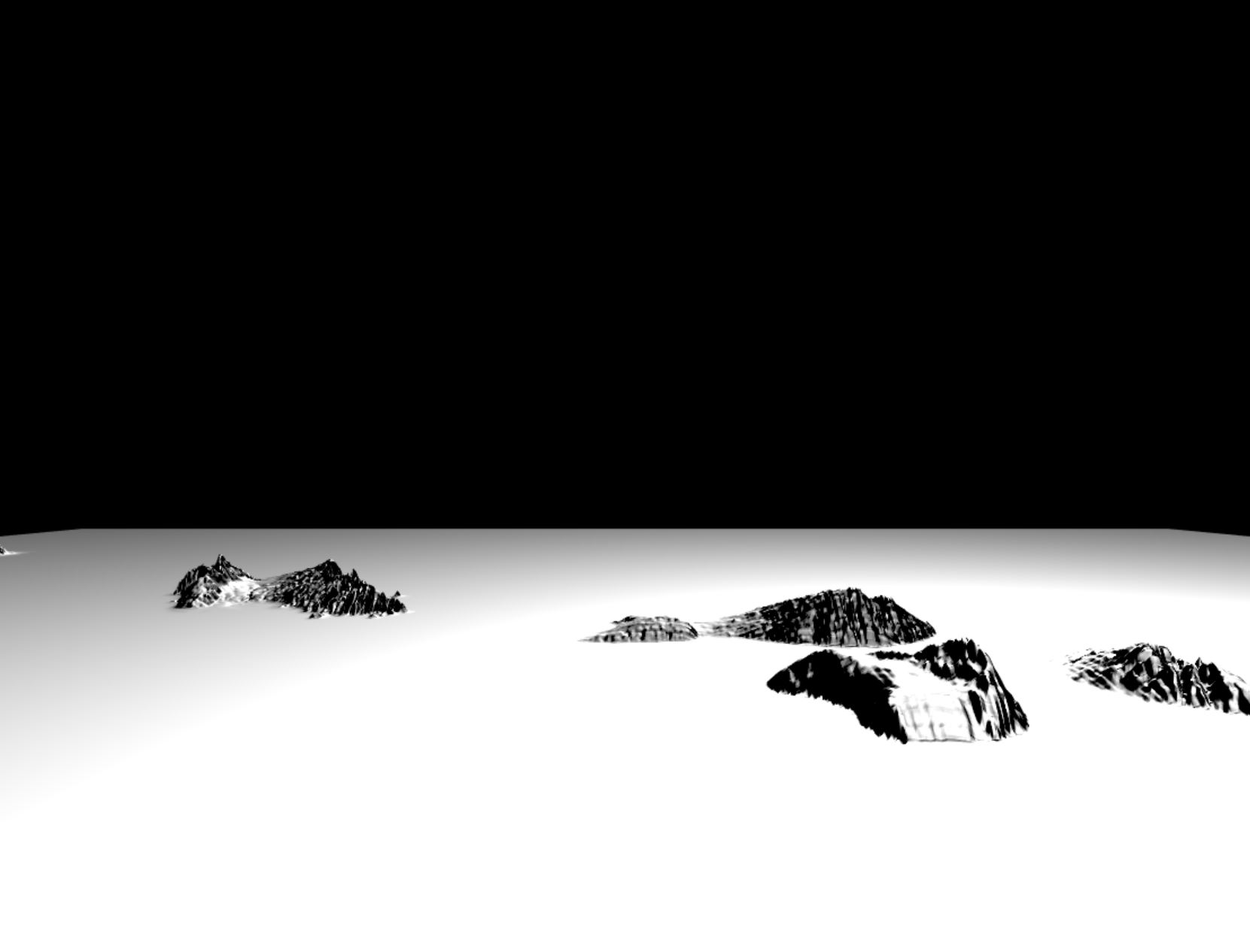
Add the Normal Map
Now in a very similar way to how we just added the displacement map, let's add the normal map. Again we call useLoader and store the results in a variable, but this time we use the normalMap prop instead of the displacementMap prop to attach the texture. You may be sensing a pattern. Watch how the shading of the deformed geometry takes on life as shadows appear on the previously flat surface.
import React, { Suspense } from "react";
import { Canvas, useLoader } from "react-three-fiber";
import * as THREE from "three";

import { Plane } from "drei";
import "./styles.css";

const Terrain = () => {
  const height = useLoader(THREE.TextureLoader, "elevation.png");
  const normals = useLoader(THREE.TextureLoader, "normals.png"); // highlight-line

  return (
    <group>
      <Plane
        rotation={[-Math.PI / 2, 0, 0]}
        position={[0, -3, 0]}
        args={[64, 64, 1024, 1024]}
      >
        <meshStandardMaterial
          attach="material"
          color="white"
          metalness={0.2}
          normalMap={normals} // highlight-line
          displacementMap={height}
        />
      </Plane>
    </group>
  );
};

export default function App() {
  return (
    <Canvas>
      <pointLight intensity={2} position={[7, 5, 1]} />
      <Suspense fallback={null}>
        <Terrain />
      </Suspense>
    </Canvas>
  );
}
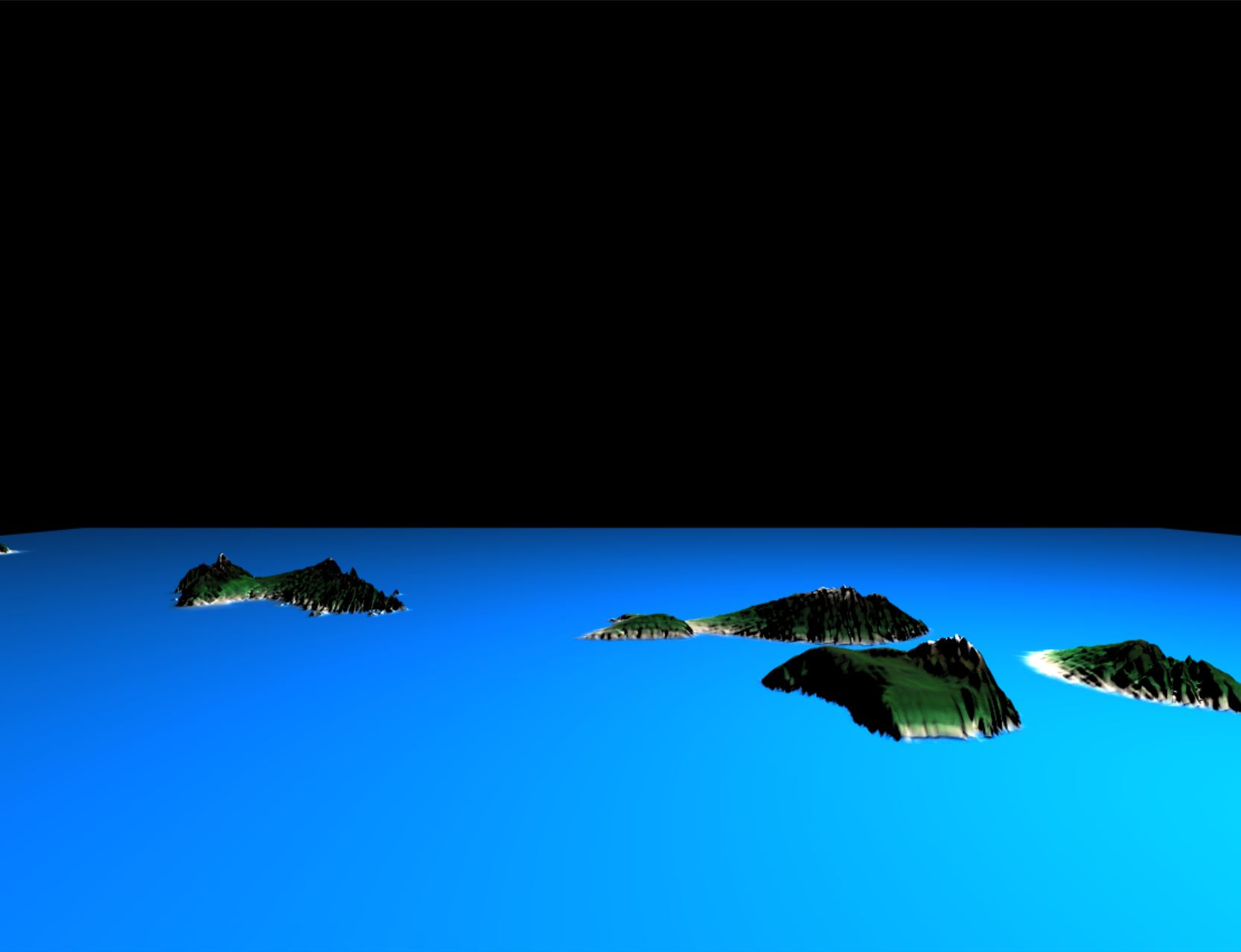
Now we're getting somewhere! You should see your islands emerging from the sea just like the image below.
Add the Color Texture
Finally let's add the color map to complete the texturing phase. This time the prop we attach the texture to is just called map.
import React, { Suspense } from "react";
import { Canvas, useLoader } from "react-three-fiber";
import * as THREE from "three";

import { Plane } from "drei";
import "./styles.css";

const Terrain = () => {
  const height = useLoader(THREE.TextureLoader, "elevation.png");
  const normals = useLoader(THREE.TextureLoader, "normals.png");
  const colors = useLoader(THREE.TextureLoader, "colors.png"); // highlight-line

  return (
    <group>
      <Plane
        rotation={[-Math.PI / 2, 0, 0]}
        position={[0, -3, 0]}
        args={[64, 64, 1024, 1024]}
      >
        <meshStandardMaterial
          attach="material"
          color="white"
          map={colors} // highlight-line
          metalness={0.2}
          normalMap={normals}
          displacementMap={height}
        />
      </Plane>
    </group>
  );
};

export default function App() {
  return (
    <Canvas>
      <pointLight intensity={2} position={[7, 5, 1]} />
      <Suspense fallback={null}>
        <Terrain />
      </Suspense>
    </Canvas>
  );
}
Add the Sky, some Atmospheric Fog, and Orbit Controls
Wow, we're done with the texturing and it should already look pretty good, but let's just make a few little improvements.
We can add a sky and some atmospheric fog to tie the bright tropical vibe together. Also we can add orbit controls to the scene so we can navigate the camera around.
We can add the OrbitControls and the Sky easily by importing components of the same name from drei and just dropping them in the scene. Just make sure the sun has the same coordinates as the light by setting the sunPosition prop on the sky. If you don't do this everything will still work but the shadows and lighting will look out of place compared to the position of the sun in the sky.
To add the fog we just add a fog component inside the Canvas and give it 3 arguments. A color, a "near" value which is the distance where the fog starts to become visible and obscure objects, and the far value which is where the fog will stop obscuring any objects past that point.
import React, { Suspense } from "react";
import { Canvas, useLoader } from "react-three-fiber";
import * as THREE from "three";

import { Plane, OrbitControls, Sky } from "drei"; // highlight-line
import "./styles.css";

const Terrain = () => {
  const height = useLoader(THREE.TextureLoader, "elevation.png");
  const normals = useLoader(THREE.TextureLoader, "normals.png");
  const colors = useLoader(THREE.TextureLoader, "colors.png");

  return (
    <group>
      <Plane
        rotation={[-Math.PI / 2, 0, 0]}
        position={[0, -3, 0]}
        args={[64, 64, 1024, 1024]}
      >
        <meshStandardMaterial
          attach="material"
          color="white"
          map={colors}
          metalness={0.2}
          normalMap={normals}
          displacementMap={height}
        />
      </Plane>
    </group>
  );
};

export default function App() {
  return (
    <Canvas>
      <fog attach="fog" args={["white", 0, 26]} />
      <OrbitControls autoRotate />
      <pointLight intensity={2} position={[7, 5, 1]} />
      <Sky sunPosition={[7, 5, 1]} /> // highlight-line
      <Suspense fallback={null}>
        <Terrain />
      </Suspense>
    </Canvas>
  );
}
If everything went according to plan you should now have a scene just like the one from the beginning of the tutorial! You could use this technique to make all kinds of different landscapes just by choosing different height maps and by changing up your color gradient mapping. You could even manually paint some rivers and lakes onto your color map after you create it. Try experimenting and discover your own cool landscape ideas.